7 Steps for Bridge Designers
To Make Bridges Works of Art
St. Croix River Crossing, Stillwater,MN - Houghton, WI
1. Look and Listen
Bridge are public works, owned by the taxpayers that fund them. That makes the taxpayers the clients of the design team. Many bridge controversies result from the sponsoring agency not knowing what their constituents actually want. Before the design team can start its members must understand all the criteria the structure must meet and all the concerns that will act on it. The quantitative constraints, like pavement width and utility loads, are important as are the qualitative concerns, like minimizing environmental impacts. But meeting community aspirations, even non-engineering aspirations in areas like urban design and historic preservation, are even more important.
There is no substitute for first-hand knowledge of the site, the owner, and the people who will use the bridge and those who will be its neighbors. The process must be more than just examining maps and taking photographs. Bridges being public works, gaining this knowledge must necessarily involve many people. Take the time to hold the structured interviews and meetings with participating agencies and communities to gather their views.
As the end of this process, develop a Design Intention or Vision summarizing how the bridge will address all the criteria and concerns the structure must answer. Think of it as a series of goal statements. Then circulate the Design Vision among the design team and the community stakeholders, and amend the Vision as necessary until a consensus supports it.
Example: A National Wild and Scenic River
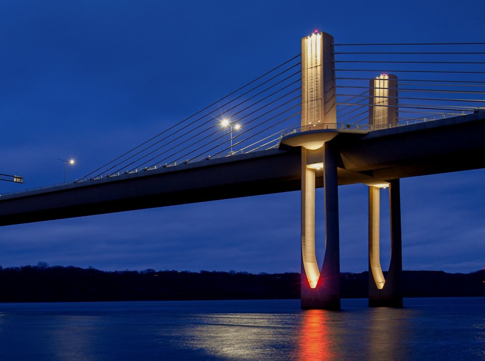
The St. Croix River forms the boundary between Minnesota and Wisconsin. and is a National Wild and Scenic River. Developing a Design Vision took 16 years of discussion among the two states’ transportation agencies, environmental and historic agencies, the National Park Service and the communities on each side of the river. The Vision required that the number of piers in the river be no more than six, that a pedestrian and bike crossing be provided, that the bridge be as transparent as possible and that the bridge components recall the water-related vegetation bordering the river.

[Note the reflections from the water surface on to the bridge.]
St. Croix River Crossing, Stillwater. MN-Houghton, WI, Example: Community-Driven Needs
In addition to adding two additional lanes to Route 9, the new Ken Burns Bridge needed to allow additional vertical clearance for sail-boaters on Lake Quinsigamond and provide viewing platforms for the frequent rowing races on the lake. The finish line for the races is the Bridge.

Ken Burns Bridge, Worcester-Shrewsbury, MA
2. Work as a Team
Everyone knows how to work as a team with fellow professionals. Doing so with community members may be unfamiliar, but in fact is not all that different, and treating the community as full-fledged members of the design team is crucial to success. Start with an all-inclusive process, gathering concerns and concepts from all on an equal basis. Treat everyone’s ideas and concepts with respect. Make sure they all get listed on the record. Evaluate them all, even the farfetched ones. Sometimes the germ of a really valuable concept is hidden within a “crazy” idea. Report back to the team on all of ideas, so that everyone knows that their ideas are being taken seriously. At this point the community member of the team are teaching the professionals about the community, and the professional are teachin the community about how to build bridges.
Example: A Comprehensive Process
Replacing the Woodrow Wilson Bridge across the Potomac River in Washington, DC involved the state DOTs of Matyland and Virginia, the District of Columbia, the City of Alexandria, VA, Prince Georges County, MD and the National Park Service. As this diagram shows, the process began with a listing of all of the issues, in whatever category. Then all the concepts being suggested by whichever participant were also listed. All were evaluated, the most promising combined into specific alternatives and then whittled down by an all-inclusive steering committee until a final solution emerged.
Example: Building Trust by Making Sure Everyone Understands
Community members don’t understand engineering drawings. In fact, standard elevation and section drawings can even mislead engineers. Every significant option and decision must be analyzed using computer-generated (for accuracy) 3D drawings, physical models, or for important details like railings, full-size mockups. Everyone can understand them, and everyone knows what they are getting. No more unwinnable arguments between people who have completely different mental pictures of what is being discussed.

An early pier study for the Woodrow Wilson Bridge
3. Start with the Alignment
The position of the bridge within its surroundings, the distance of the bridge above the terrain or water, the distance from the bridge to nearby features, the very shape of the bridge itself is determined by its horizontal and vertical alignment. The alignment is often established before the bridge design starts, with no concern for the appearance of the bridge. Frequent flaws include curves, especially vertical curves, that are too short, and horizontal and vertical curves that are not coordinated with each other. Bridge designers need to investigate improvements in the alignment that will improve the appearance of their bridges, then do their best to get those improvements adopted.
Example: Island Hopping
New Jersey 52 Bridge extends two miles across Great Egg Harbor Bay, an estuary open to the Atlantic Ocean with low, marshy islands. The Bridge connects the mainland at Somers Point to the barrier island of Ocean City. In this flat marine environment the vertical and horizontal curves of the alignment are clearly visible. The curves were lengthened and the vertical curves overlaid on the horizontal curves so that the bridge became a graceful “ribbon in space” tying the island to the mainland.

[At night, to further tie the island to the mainland, the pier lighting creates bands of different color that move across the bay.]
NJ52 over Great Egg Harbor Bay, Somers Point-Ocean City,
Example: Third Crossing of the Cataraqui River an Rideau Canal
The Third Crossing of the Cataraqui River spans the Cataraquie River, an arm of Lake Ontario, and the Rideau Canal, a UN World Heritage site. The Bridge adjoins an island burial site sacred to Canada’s First Nations. It connects streets on either side of the river which do not align with each other and which are near water level. The Bridge also has to rise about 30 feet to allow vertical clearance for the Rideau Canal. Two horizontal curves and three vertical curves are necessary to make all of this happen. The curves were stretched and coordinated so that the whole bridge, end to end, is a continuous and sinuous 3-dimensional curve. The alignment sweeps the eyes of users over the Cataraqui scene and the wetlands and residential areas of Hamilton bordering it.

3rd Crossing of the Cataraqui River, Hamilton, ON
4. Develop Many Options
Finding the right solution means considering a wide range of possibilities. The process is called “Conceptual Engineering”. It is often short-changed. Instead, designers do what someone else has done before someplace else. Bridge design has long been plagued with individual or institutional preferences and assumptions about what bridges “should” look like, or, an attitude of “we’ve always done things this way”. Remember, by definition, improvements come from the realm of ideas not tried before. Every site is different; every community is different. Designers need to begin with a clean slate and an open mind and look at a wide range of possibilities. The more ideas that are considered, the more likely it is that the selected concept will have that unique “fit” which will make the bridge a valued landmark in the community and a work of Bridge Art.
Example: Making Electrical Connections
The Veterans Memorial Bridge in Bismarck, ND connects the eastern and western halves of North Dakota across the Missouri River. The Bridge also carries the cables for the main east-west connection of North Dakota’s electrical grid. The previous bridge carried this connection as a cat’s cradle of wires and brackets tacked onto the side of the structure. The North Dakota DOT and the community wanted these wires concealed. The bridge uses four steel box girders to carry both vehicular traffic and the electrical cables, which are hidden within the box girders. The electrical switch gear involved is concealed within the bridge abutments.

Veterans Memorial Bridge, Bismark, ND,
Example: Two Different Structural Systems
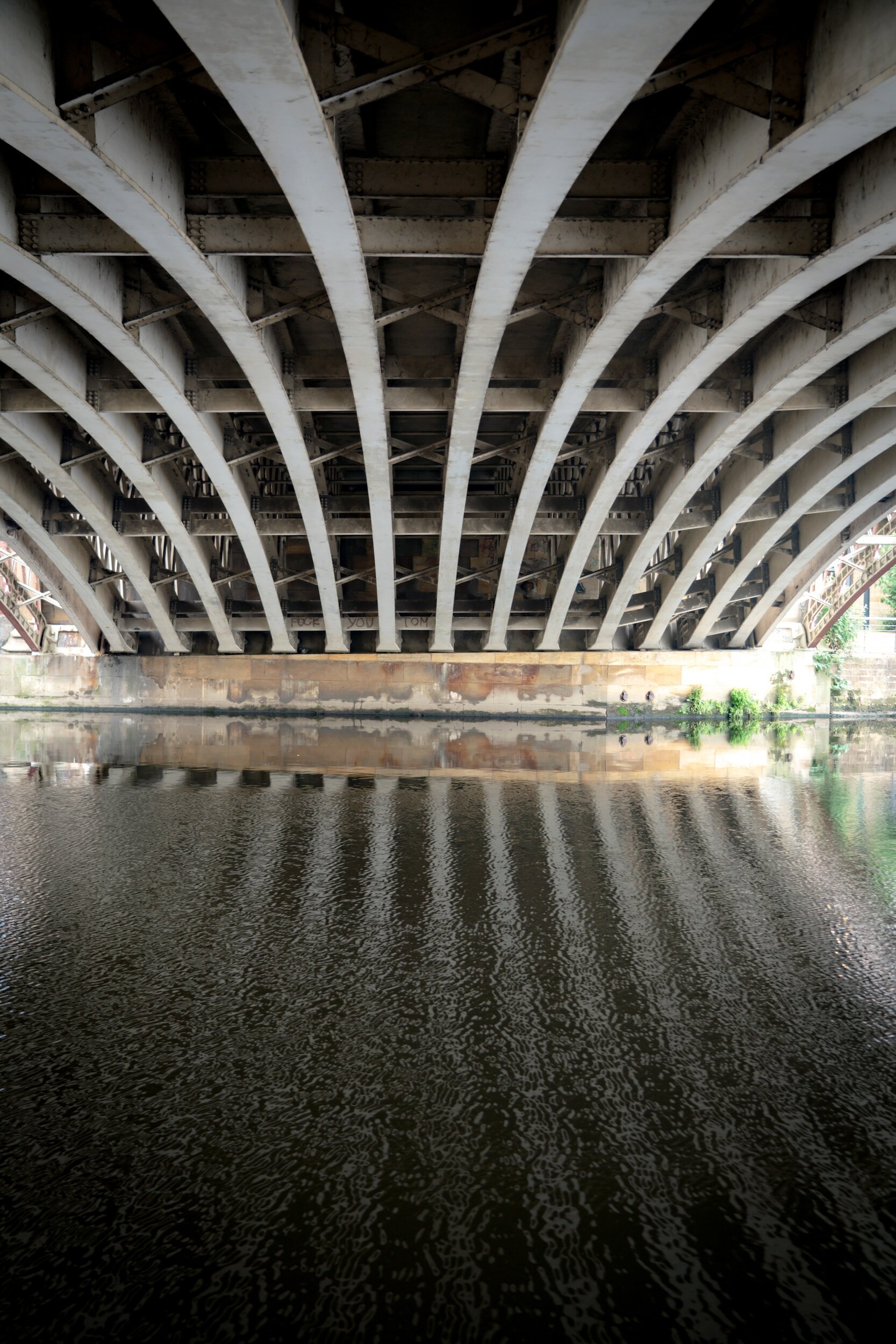
The distant two thirds of this Bridge spans a parking lot, Interstate 70, the Colorado River and Union Pacific Railroad. The near third forms spans a half-block of Grand Avenue, Glenwood Springs’ main street, which is used for community events and warm weather seating by the restaurants in the adjoining buildings. To meet the different needs of the areas below the Bridge, it combines 2 different structural system: 3 steel box girders over the parking lot, Interstate, river and railroad, and a solid concrete slab over the pedestrian street. The bottom of the slab becomes the “ceiling” of an outdoor “room”. The noise and vibration from the 18 wheelers passing directly overhead is blocked by 3 feet of concrete.
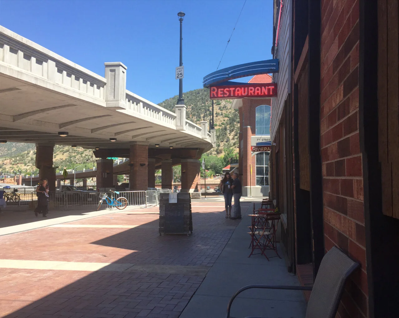
Grand Avenue Bridge, Glenwood Springs, CO
5. Compare Options using the Characteristics of Bridge Art
Most Bridges can be seen from many locations. The first step is to decide which are most important and what aspect of the bridge will be most visible from each. Then develop visualizations of each option from each viewpoint (by computer for accuracy). Visualizations allow all involved, engineer and community stakeholder, to understand and compare the visual impact of the options. Look for simplicity (the options with fewest visual elements). Look for elements that demonstrate how the bridge works structurally: how do loads get to the ground? Remember trees: the thin branches support the leaves, the thick branches support the thin branches, the trunk supports the thick branches. The load path is clear and direct. Finally, look for details which attract the eye and intrigue the mind. The goal is to identify the option which best embodies efficiency, economy and elegance.
Example: Telling the Structural Story
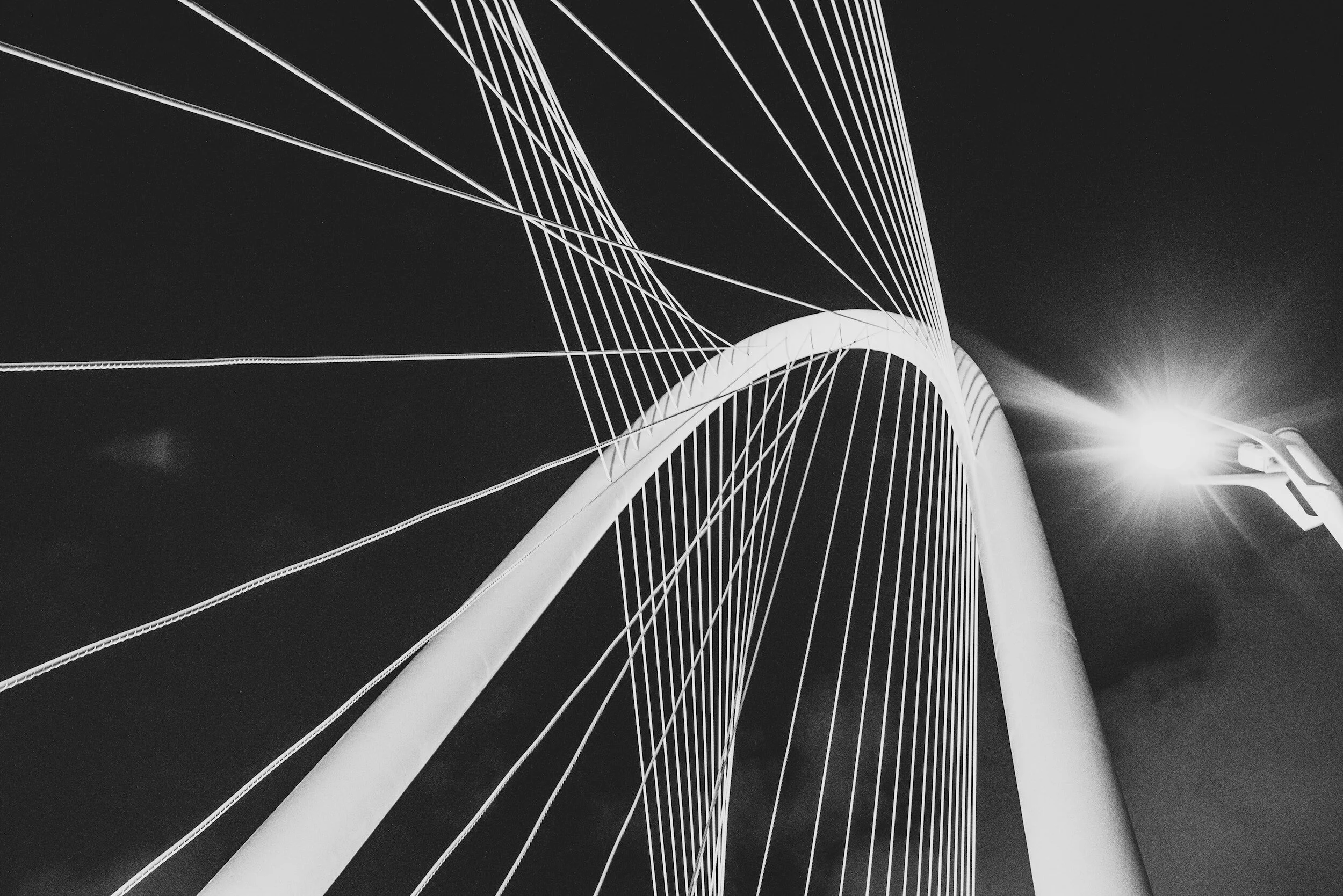
A clear load path: the cables support the roadway, the towers support the cables. Minimal visual elements: 1 roadway, 16 cables, 2 towers. The slit in the towers gives them the flexibility to respond to the lengthening ofthe deck due to temperature changes. The different color of the upper center of the tower recognizes the tower’s separation into two halves. About as simple, clear and elegant as it gets.

St. Croix River Crossing, Stillwater, MN - Houghton, WI,
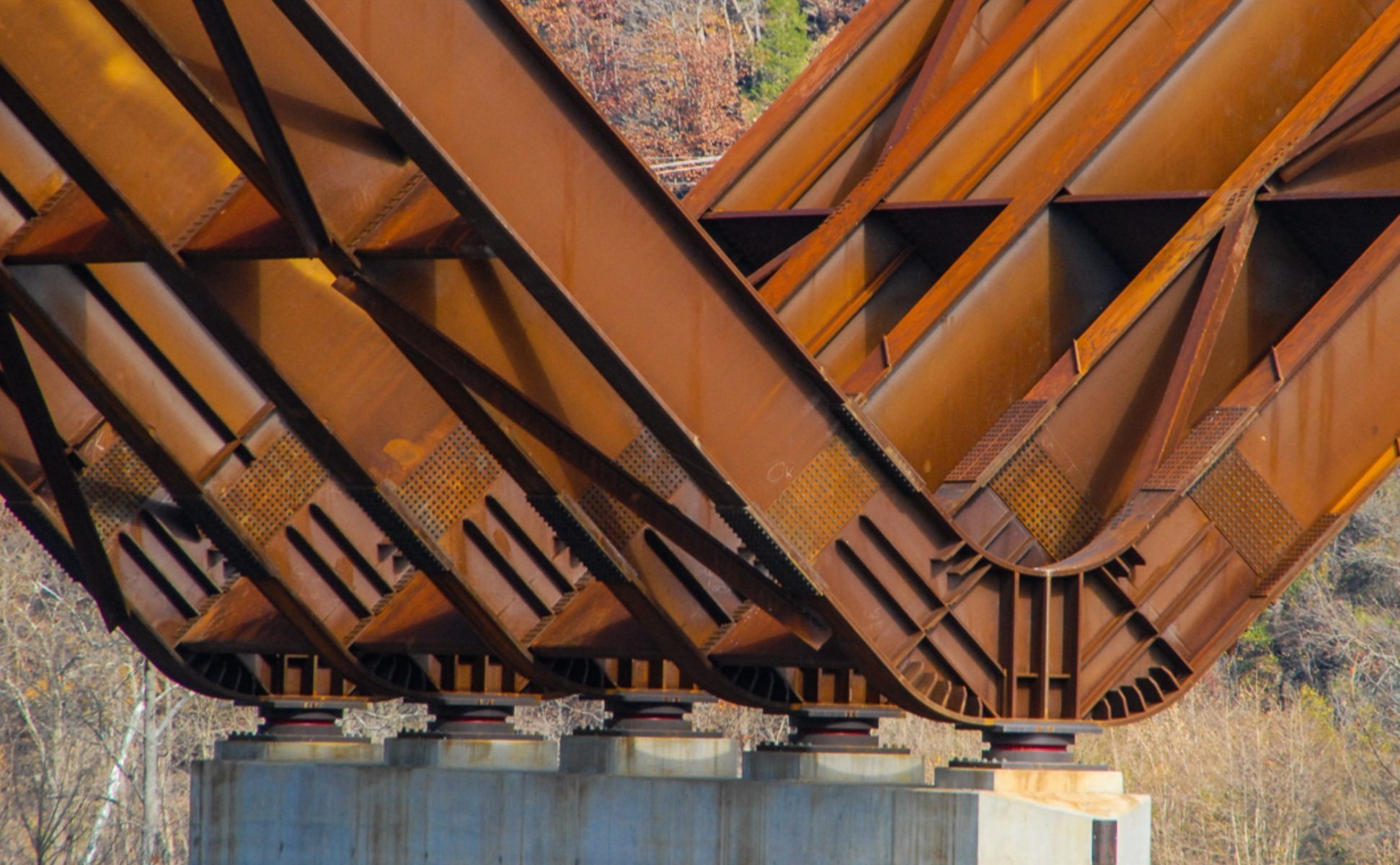
Example: A Clear Load Path
The structural system for the Veterans Memorial Bridge over the Missouri River in Bismarck, ND uses 4 steel box girders to span 300 feet between piers. The piers start from water level as 2 shafts divided by a vertical groove. Each half is differentiated further by being in different planes, so they reflect light a little differently. (In plan section the piers are elongated hexagons.) As the piers rise the each half flares outward and they separate to match up with each box girder. It is perfectly clear which part of each pier carries each box girder, and people can easily follow the load down to the water.
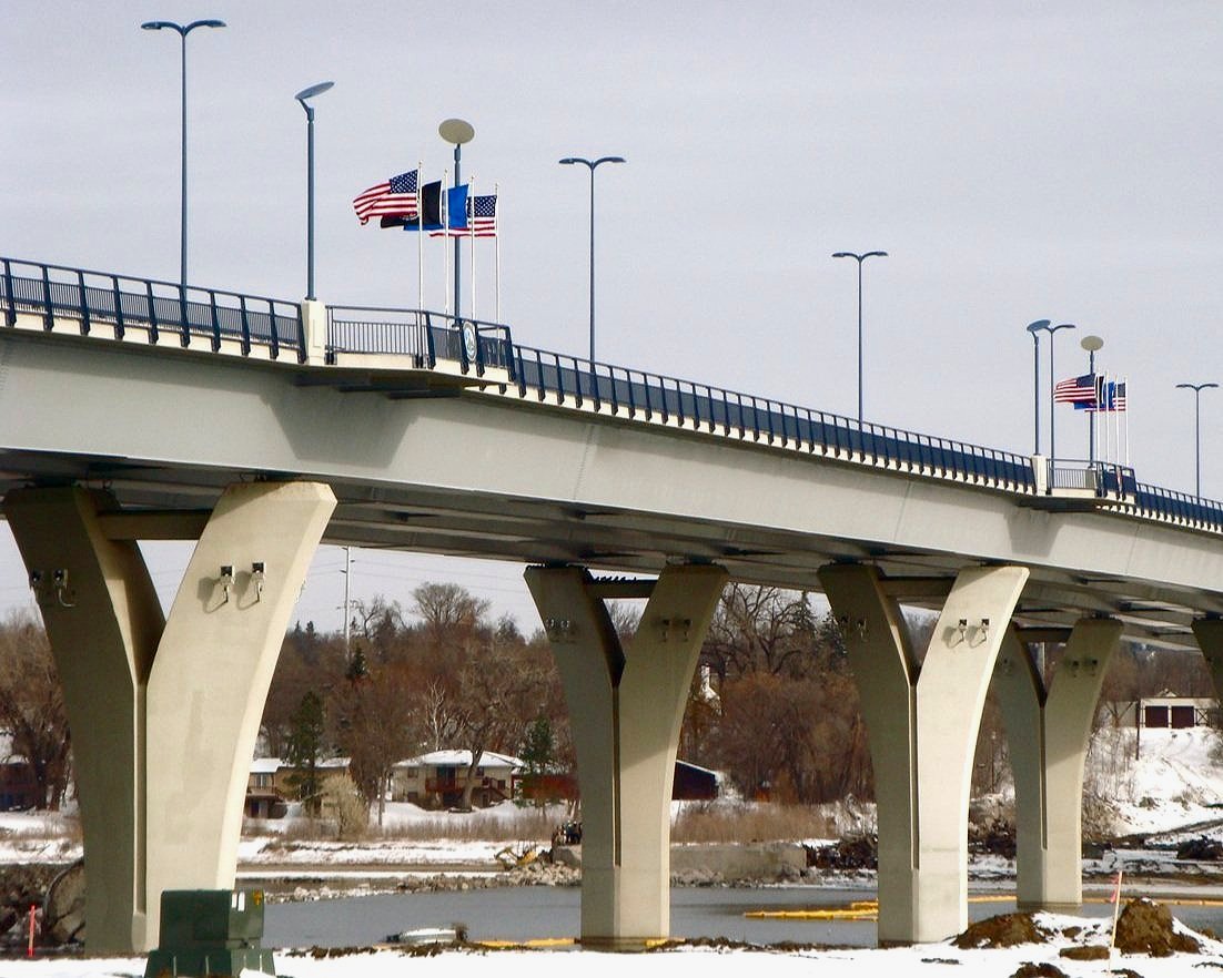
Veterans Memorial Bridge, Bismarck, ND, Fredederick Gottemoeller
6. Design the Selected Option to Bring Out its Strong Points.
Only after a Final Concept has been determined can detailed design and calculation be started. Now is also when details like railings, colors and lighting can be added. These elements must be visually supportive of the Design Vision and Final Concept while making the bridge richer and more interesting to observers. The details must also be tested with 3D visualizations and even full-scale mock-ups. Colors should be picked on site from large sample panels; picking colors in the office from 3” x 5” color chips doesn’t work.
If this phase is assigned to a new team of final designers, the original design team and community stakeholders that developed the Design Vision and selected the Final Concept must continue to be involved.
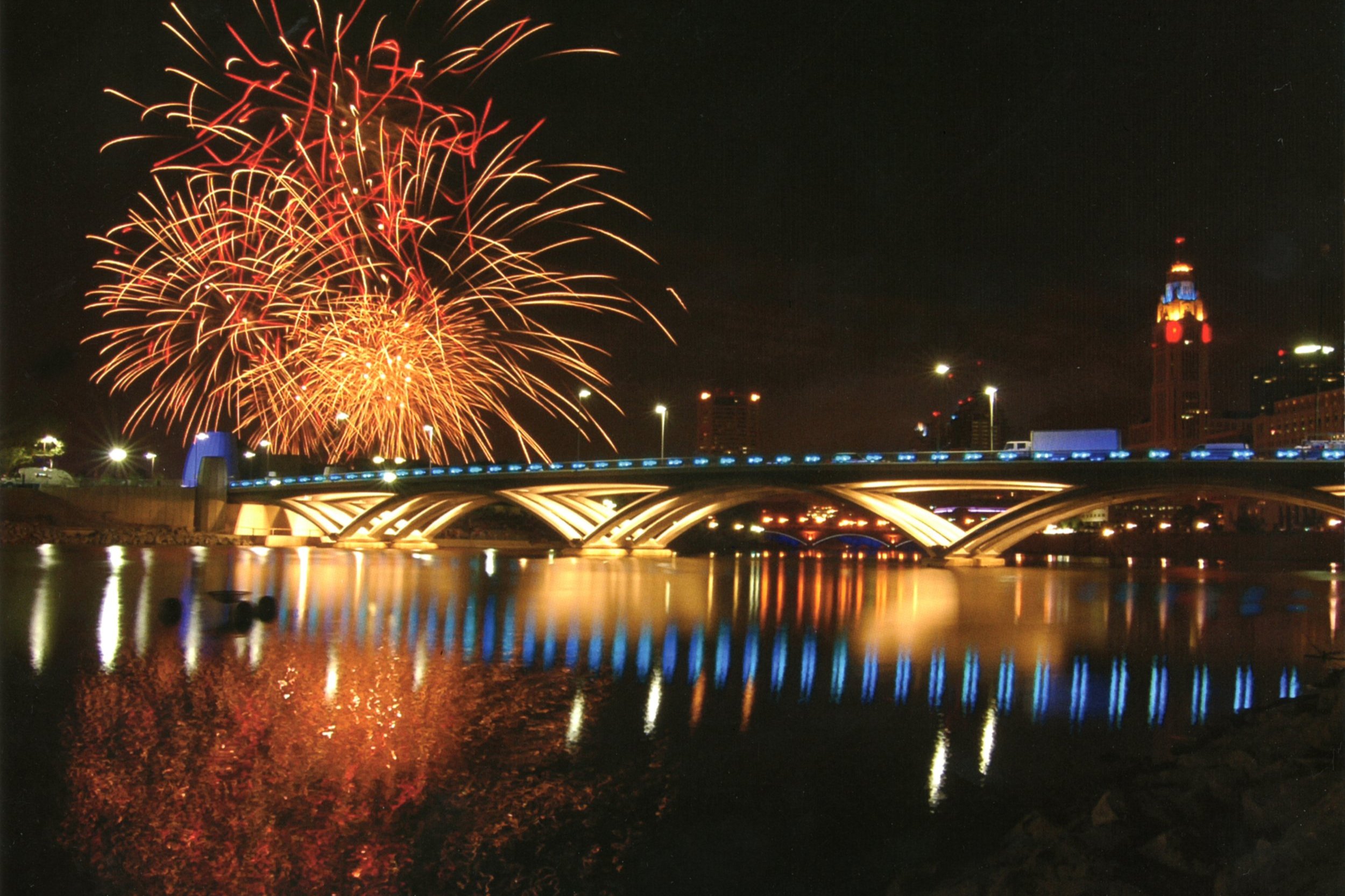
Example: Focus Attention on Load Transfer
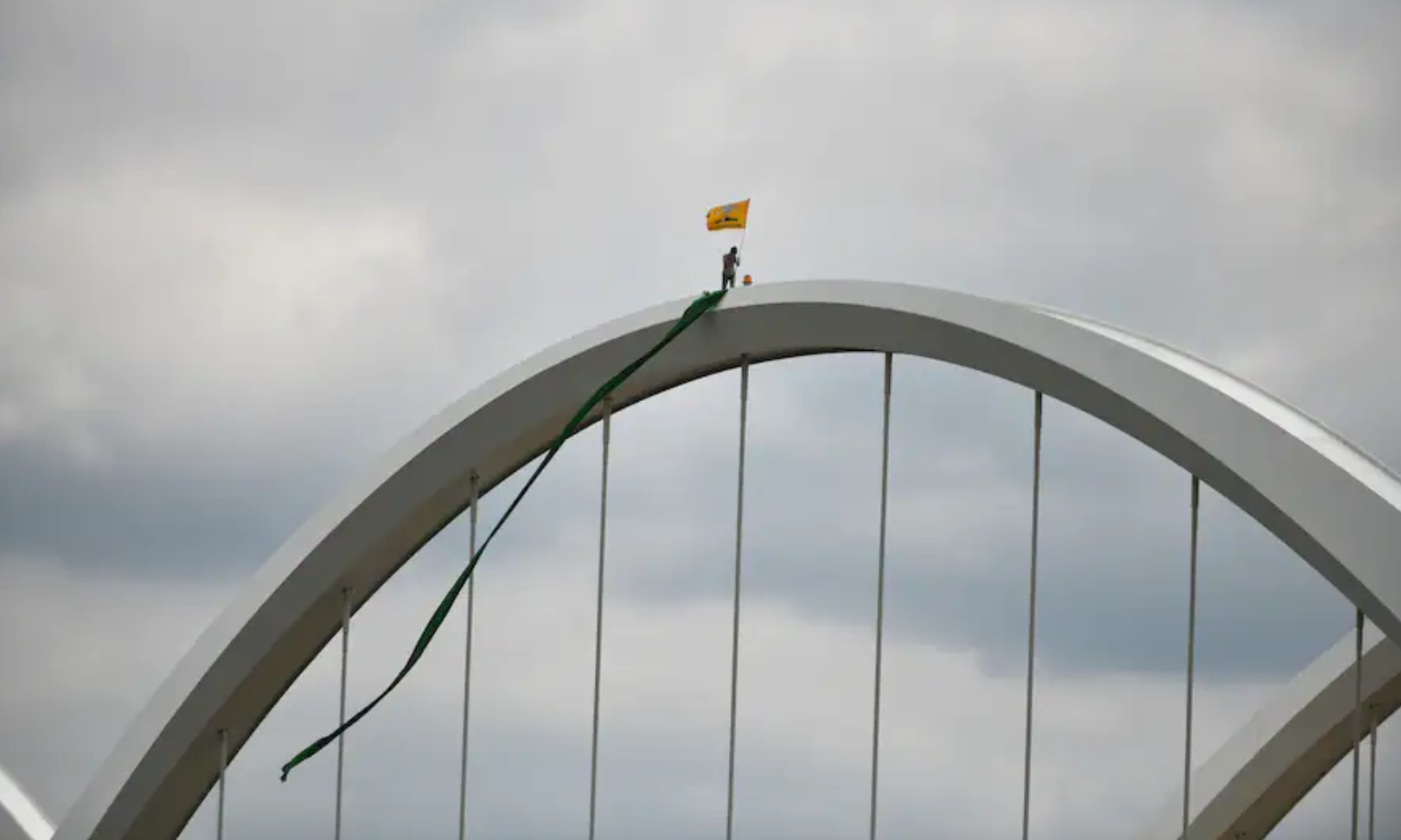
At Rich Street the loads follow the arches to the point where the arches join atop their support pad. There a stainless steel “debris deflector” provides a flash of metalic reflection that draws people’s attention to the point of load transfer.

Rich Street Bridge, Columbus, OH
Example: Lack of Color adds Variety
Picking White as the color for the Clearwater Memorial Causeway allows the bridge to reflect whatever color the strong Florida sunlight is producing at a given moment. At midday the bridge picks up the aqua of Clearwater Bay and the dynamic sparkle of the water surface. At sunset the bridge picks up the colors of the sky and clouds.
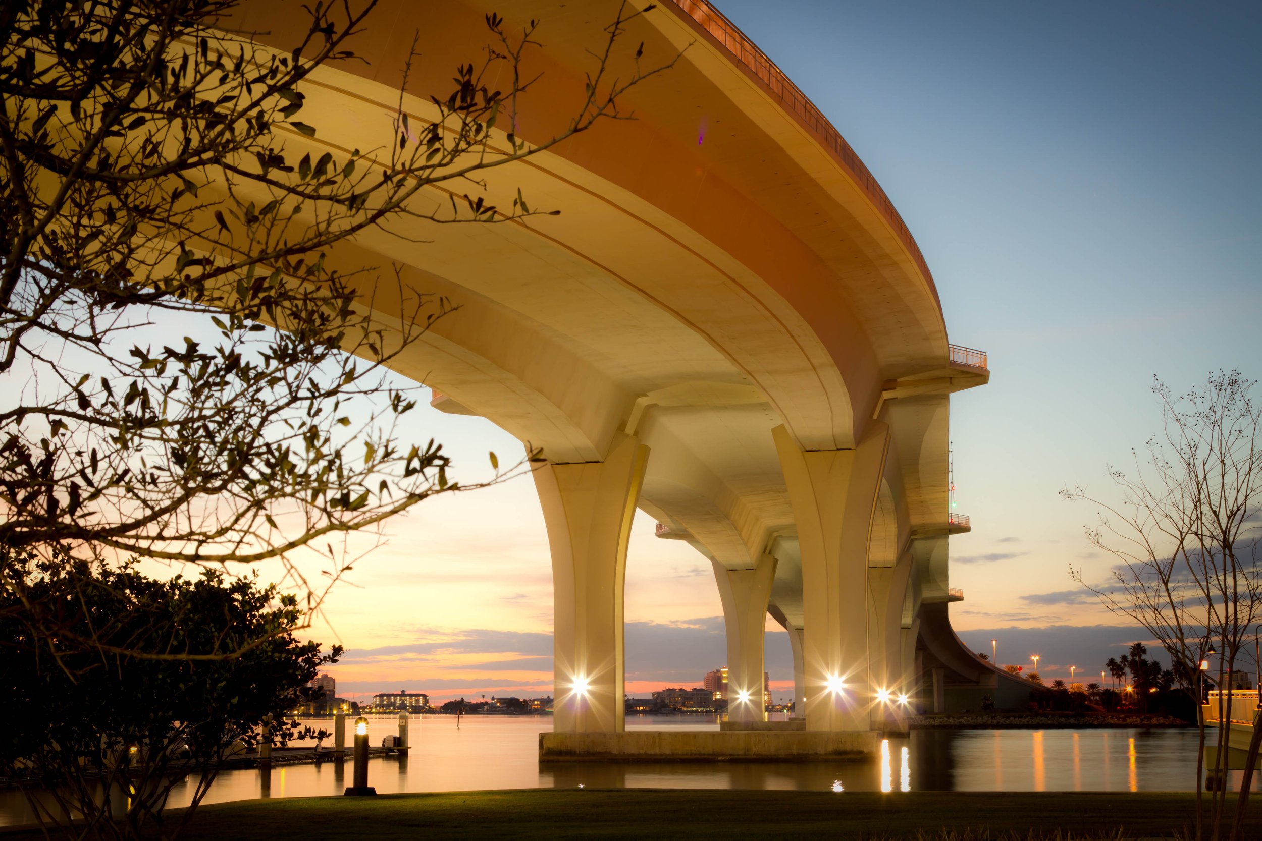
Clearwater Memorial Causeway, Clearwater FL
7. Make sure the Design Vision survives Construction
Construction often brings to the surface issues which were inadequately recognized earlier or new ideas developed by the construction team. These ideas must be handled in ways that extend and enhance the original design vision. Doing so requires that the original community stakeholders and design team continue to be involved during construction.
Example: Different Lighting
The Selected Concept for the Ken Burns Bridge included linear LED lighting elements outlining the arches. The elements were to have the ability to change colors. The contractor was concerned about the durability and repairability of the linear LED fixtures, and proposed instead LED floodlighting of the arches. Since the floodlights could also be programmed to project various colors, the community advisory panel accepted this change. The bridge lighting is programmed to change color to recognize different seasons, holidays and community events.
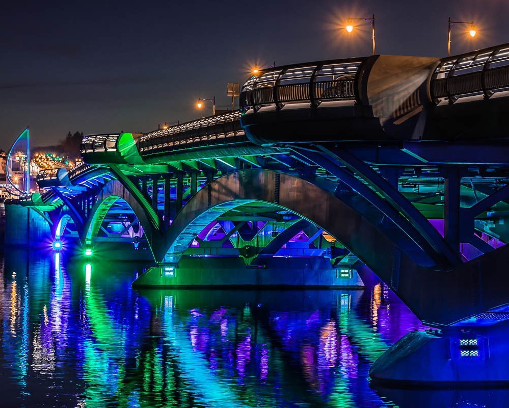
Ken Burns Bridge, Worcester - Shrewsbury MA
Example: Different Wall Feature
The US 61 Bridge across the Mississippi River in Hastings, MN also spans Second Avenue, the town’s historic main street. The Design Vision and the final design for the bridge called for facing the abutment wall adjoining Second Avenue with an art work acceptable to the Community Advisory Committee. The contractor found a local artist who uses stone of different colors to create durable exterior murals. He proposed a mural depicting the town’s history. It was enthusiastically approved by the Advisory Committee.
US 61 over the Missississippi River, Hastings, MN
Celebrate Success!
If the previous steps have been done well, the community will have been involved in each step, will understand all the reasons behind the design and will realize that their preferences have guided the outcome. The result will be the most satisfying outcome of all. They will say:
“We did it ourselves”!
These 7 Steps condense and summarize a complex process. For more depth and detail consult:
Frederick Gottemoeller, Rich Street Bridge, Columbus, OH